Killswitch PCB
Project Overview
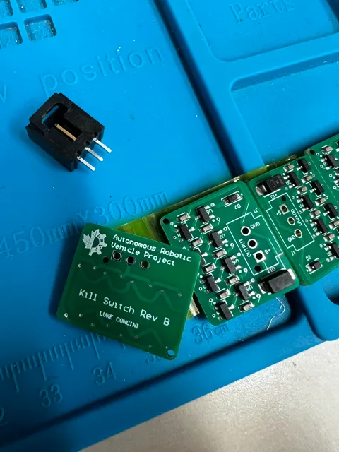
I designed a custom printed circuit board (PCB) that uses Hall-effect sensors to detect the presence of a magnet through a metal hull for an autonomous submarine. The project, part of my work with the Autonomous Robotic Vehicle Project (ARVP), aimed to upgrade a previous system. The board ensures diver safety when swimming with the robot, as it allows shutdown of the robot’s electrical system by simply removing an external magnet from the hull.
Design and Testing Process
The design of the board involved choosing appropriate components, specifically using flux calculations to find the appropriate trip and hysteresis values for the Hall effect sensor. The chips use an open-drain output to signal magnet presence. I used Altium Designer to add the components with appropriate footprints and symbols, build the circuit, and do the layout the PCB.
Upon ordering and assembling the boards and testing continuity, I breadboarded a simple LED circuit and tested bringing the magnet close to the hull. Each of the sensors operated correctly with 100% accuracy.
The board integrated well with the rest of the electrical system, requiring only a new mechanical mount.
Skills and Tools
I learned about:
- PCB design for manufacturing
- Breadboarding
- PCB assembly (soldering, crimping, etc.)
I used these tools:
- Altium Designer
- JLCPCB component database
- Various testing equipment